Types of contour lines: How to Read a Topographic Map? Common Topographic Map Symbols.
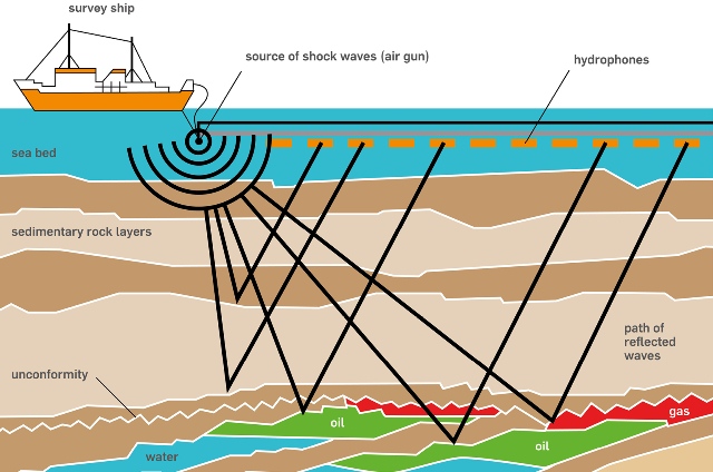
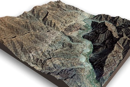
A topographic map is printed on a flat piece of paper yet it provides a picture of the terrain and manmade features through the use of contour lines, colors, and symbols. Contour lines represent the shape and elevation of the land, such as ridges, valleys, and hills. Colors and symbols are used to represent other features on the land, such as water, vegetation, roads, boundaries, urban areas, and structures.
This chapter starts with tips on how to read the margins of a topographic map. Then it describes how to interpret contour lines. Finally, it covers how to estimate slope, aspect, acreage, distances, and percent contained using a topographic map

What is a topographic map?
Common Topographic Map Symbols:
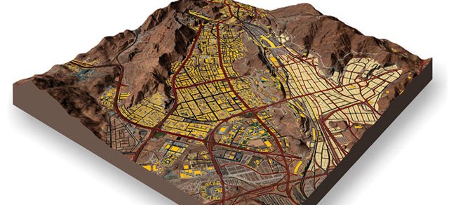
A topographic map is a detailed and accurate illustration of man-made and natural features on the ground such as roads, railways, power transmission lines, contours, elevations, rivers, lakes and geographical names.
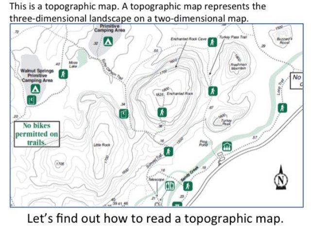
The topographic map is a two-dimensional representation of the Earth’s three-dimensional landscape. The most frequently used topographic map is at a scale of 1:50 000.

Reading a topographic map worksheet
Different maps serve different purposes. If you’re trying to drive from Point A to Point B, a regular road map is a way to go. But if you’ve strayed from the road, perhaps on a backpacking trek, you need to see the terrain and the contours of the land. And that means you need to be able to read a topographic map.
Common Topographic Map Symbols: What’s the difference between a topographic map and a regular map?
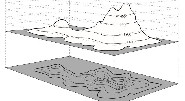
In a nutshell, topographic maps allow you to see a three-dimensional landscape on a two-dimensional surface. These maps show the land’s contours, elevations, mountains, valleys, bodies of water, vegetation and more. This contour and elevation information distinguishes them from other maps.
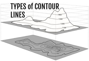
Types of contour lines
The ability to fuse these major factors is the most critical skill one can learn when using a topographic map. The primary purpose of a topographic map is to accurately represent the shape of the Earth’s surface, but the utility doesn’t stop there. Topographic maps also represent streets and trails, vegetation, streams, and every type of feature that may positively or negatively impact your ability to navigate through the terrain.
Contour lines on a map
Common Topographic Map Symbols: Contour lines are imaginary
They are map artifacts used to represent paths or segments of Earth at an equal elevation. These paths and segments are presented as elevations (vertical distance above or below sea level) and reliefs (the shape of terrain features on the Earth’s surface).
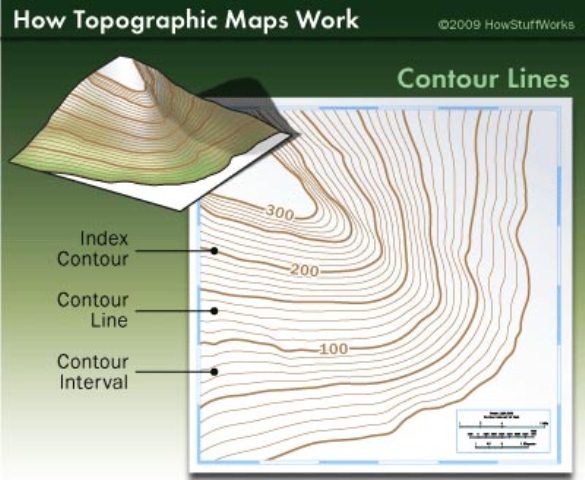
Not all contour lines are created equal. Heavier contour lines are known as indexed contour lines and are normally numbered showing elevation. Typically every fifth contour line is an index.
Lighter contour lines, that fall between indexed lines, are known as intermediate contour lines. These lines do not have their elevation given and are found in sets of four between indexed contour lines.
Finally, when the terrain is expansively flat, cartographers will often include supplementary contour lines, which are dashed lines indicating an elevation that is half of the elevation between the contour lines surrounding it. They are typically found where there is little change in elevation.
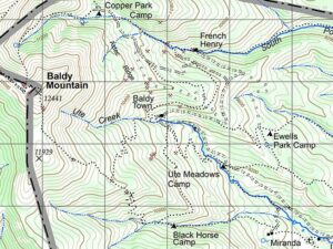
How to read contour lines
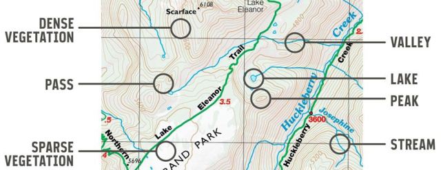
Contour lines indicate the steepness of the terrain. Contour lines connect points that share the same elevation: Where they’re close together (they never intersect), the elevation is changing rapidly in short distance and the terrain is steep. Where contour lines are wide apart, the elevation is changing slowly, indicating a gentle slope.
Contour lines also indicate the shape of the terrain. Roughly concentric circles are probably showing you a peek, and areas between peaks are passes. Studying a topo map of a familiar area is a great way to learn how to match terrain features with the contour lines on a map.

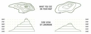
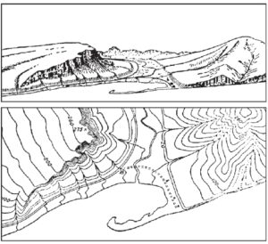
Interpreting Contour Lines
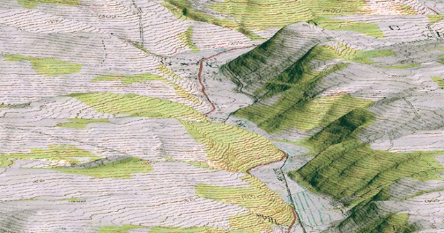
Contour lines on a map show topography or changes in elevation. They reveal the location of slopes, depressions, ridges, cliffs, the height of mountains and hills, and other topographical features. A contour line is a brown line on a map that connects all points of the same elevation. They tend to parallel each other, each approximately the shape of the one above it and the one below it. Compare the topographic map with the landscape perspective.

Topographic map colors
Common Topographic Map Symbols: It’s important to know what kind of terrain and environment you’re traveling into and what the map of that area is telling you.
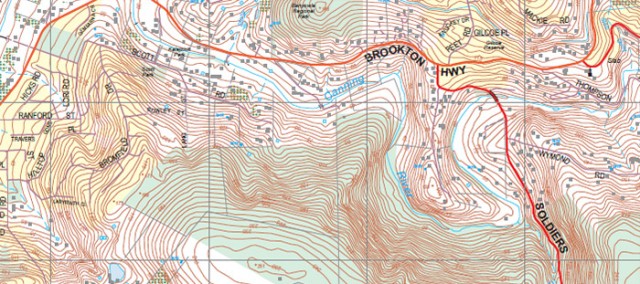
The color brown is used to denote most contour lines on a map, which are relief features and elevations. Topographic maps use green to denote vegetation such as woods, while blue is used to denote water features like lakes, swamps, rivers, and drainage.
At higher elevations, mountains may be snow-capped year around, or the terrain may actually be a glacier. In each of these cases, contour lines are also drawn in blue. It is, therefore, possible to quickly discern that a particular route from A to B might be more treacherous than operating at a high altitude—the trek might require crampons, an ice axe, and other materials that might not be readily available once in the backcountry.
Finally, black is used to represent man-made objects, including trails. Red is used for man-made features, like main roads or political boundaries, and purple for new changes or updates on the map that weren’t previously represented. Newer maps no longer use purple, but since so many older maps exist, it’s worth mentioning.
Map scales
The map’s scale tells you how detailed your map is. A 1:24000 scale, for example, means one inch equals 24,000 inches in reality. A larger scale, like 1:65,000, means that a map covers a larger area, but that it will have less detail.
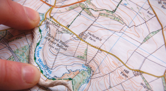
Maps also have a representative scale to help you visualize real-world distances. You can use this scale and a string or the edge of your compass to get a rough estimate about hiking distances on your map. (Common Topographic Map Symbols)
Topographic map shading
The color similarity between features does not mean that the features are equivalent. Due north of Lake Raven is the Prairie Branch, another name for a stream. Other names that equate to a stream include kill, run, fork, and brook. What’s interesting about Prairie Branch is that it has led to the formation of a wooded marsh or swamp.
Navigating across Prairie Branch could be difficult. Since this is Texas, expect to run into water moccasins, copperheads, and perhaps the occasional alligator, among all of the other friendly animals that call Sam Houston National Forest home.
Remembering map colors is a fairly trivial task, but remembering the shadings is far more difficult given the sheer number of variations. For this reason, keeping the USGS Topographic Map Symbols–a mere two sheets of paper–behind your map can be a lifesaver. A quick reference to page four of the booklet confirms that Prairie Branch is indeed a submerged wooded marsh or swamp. (Common Topographic Map Symbols)
Latitude and longitude map
Latitude and Longitude (edges of map): Common Topographic Map Symbols
Latitude and longitude lines are indicated with fine black tick marks along the edges of the map. Topographic maps do not show the latitude/longitude lines – just the tick marks.
The numbers next to the tick marks indicate degrees (°), minutes (‘) and seconds (“).
On 1:24,000 scale maps, latitude, and longitude tick marks are indicated every 2.5 minutes.
- Longitude tick marks are on the top and bottom edges of the map and latitude tick marks are on the right and left edges. Note that the degrees may be left off (as an abbreviation) and you may only see the minute and/or second designations.
- Reference coordinates for latitude and longitude (degrees, minutes, and seconds) are black and located on the four corners of the map.
- The intersection of latitude and longitude lines are noted by cross-marks.
When reading latitude/longitude, pay close attention to the units (degrees, minutes, seconds) because it is easy to misread them. Refer to Chapters 3 and 6 for additional information on latitude and longitude.
What is a contour interval?
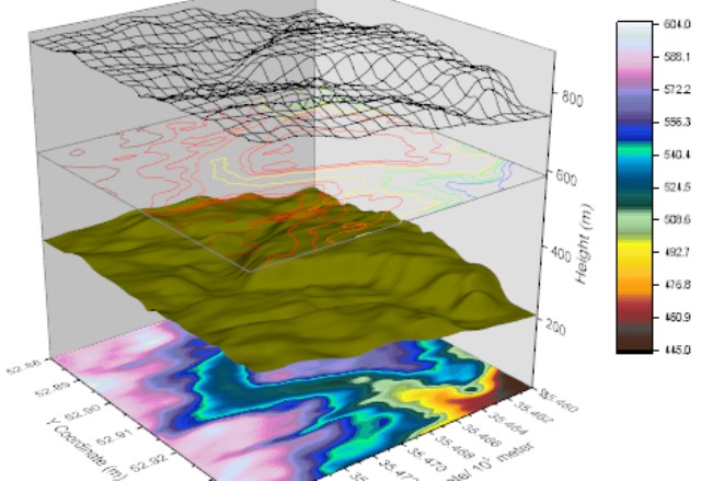
Contours maps (such as topographic maps) compress the information of a function over a two-dimensional area into a discrete set of closed lines that connect points of equal value (isolines), striking a fine balance between expressiveness and cognitive simplicity.
They allow humans to perform many common-sense reasoning tasks about the underlying function (e.g. elevation).
The contour interval is the difference in elevation between two adjacent contour lines. On USGS maps, contour intervals are usually 1, 5, 10, 20, 40, and 80 feet. If the contour interval is not printed on the map, it can be calculated.
Common Topographic Map Symbols
In cartography, a contour line (often just called a “contour”) joins points of equal elevation (height) above a given level, such as mean sea level. A contour map is a map illustrated with contour lines, for example, a topographic map, which thus shows valleys and hills, and the steepness or gentleness of slopes.
Topographic maps also have a vertical scale to allow the determination of a point in three-dimensional space. Contour Lines: Contour lines are used to determine elevations and are lines on a map that are produced from connecting points of equal elevation (elevation refers to height in feet, or meters, above sea level).
The numbers represent the elevation, the higher the number the higher you are. Usually, it’s in something like meters or feet above sea level, check the key/legend (UK/US!) which should tell you exactly what. The closer together the lines, the steeper the terrain, the further they are apart, the shallower.
For example, if your U.S. Geological Survey (USGS) map has a scale of 1:24,000, it means that one inch on the map is equal to 24,000 inches (2000 feet or 609.6 meters) in the real world. Your map’s scale legend will always be at the bottom. For USGS topographic maps, 1:24,000 is the scale most often used.

C-Map Contour
C-MAP, a leader in digital marine charting and cloud-based mapping, announced the next generation of C-MAP Contour charts, preloaded on sounders and plotters.
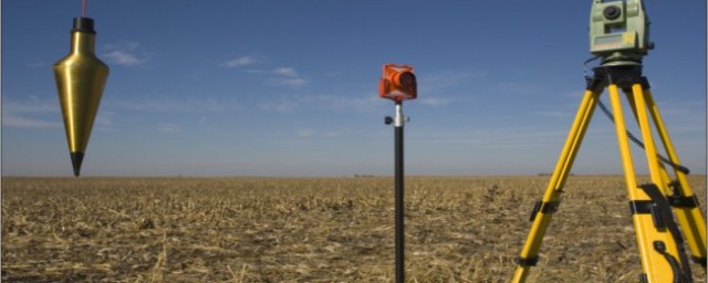
Types of Topographical Survey
While most people think of land surveys in the most basic sense—that is, the drawing of the boundaries of property—there are actually many different ways of surveying that service many different industries.
Topographic Map definition
Topographic maps offer detailed information on a particular area and are used for several types of activities such as emergency preparedness, urban planning, resource development, and surveying to camping, canoeing, adventure racing, hunting, and fishing.